Thursday, February 2, 2017

Implementing a BPM Architecture for medicine development in Pharmaceutical Industry


Dr. Roy Abraham

1. Introduction: Business Process Management deals with defining, analyzing, managing and implementing the interaction among internal systems, people and external trading partners. BPM provides a holistic approach to Software development involving technology (objective) and human behavior (subjective). In traditional systems, Business Logic (objective part) and Business Rules (subjective part) in a Business Process are tightly coupled. Hence, any requirement change in either one results redesign or re-factoring (depends on the extent of the change) of business process. However, laws, rules and regulations of certain business processes change constantly. This necessitates the decoupling or loose coupling of Business Rules and Business Logic. Business Logic is hard coded (means, business logic change depends only on requirement change). On the other hand, transient changes in rules, laws and regulations are encapsulated in Business Rules. These Business Rules may or may not need human intervention. Business Logic is implemented in Application server (for example, an EJB or IoC container). Business Rules, which need human intervention is implemented in Workflow server. Business Rules, which do not need human intervention is implemented in Rules Engine.

2. Components of BPM: The major components of BPM are described below.
a) Business Logic: Defines the objective behavior of permanent nature. In software terms, this attribute never changes unless and until requirement changes. This also implies that there is nothing absolutely permanent in software development. The core business model of the enterprise is captured in the business logic.
b) Business Rules: Defines the objective behavior of transient nature. However, this attribute changes within the confines of the requirements. This encapsulates the forces outside the enterprise which influence the core business model such as market forces and government policies. The daily or weekly promotion sale of the company or changing the sales tax structure due to government policies are few such examples.
c) Work flow: Defines the subjective behavior of transient nature. This is where the human aspect interacts with the core business model. For example, a customer agent partially forgives the overdue penalty of a customer and her supervisor completely forgives it due to good payment record of the customer.
d) Trading Partner Interaction (B2B integration): Defines the business relationship with other enterprises. In the current integrated business environment, business to business transaction is inevitable one way or the other.
e) Enterprise Application Integration (EAI): Defines the integration of various software and data assets within the enterprise. It can be legacy assets accrued over the years such as main frame or software written in C language.
f) Life cycle management: Almost every business model has to perform a sequence of tasks from inception to fulfillment, to complete the business process. It can be a claim processing, an order fulfillment of a shopping cart or a loan processing etc. BPM provides the state management of individual steps involved in the Business


Process. Figure 1: Components of BPM
g) Monitoring: The entire software development project is business requirement driven. The business requirement is stake holder driven. Hence, directly or indirectly the business manager is the ultimate stake holder of the software development. However, the business manager may not have the technical acumen to understand the complexities of the software process. She has to believe what she is told by the development team. This poses considerable challenge to the Business Manager on day to day operations of Business Process. The monitoring tools of BPM provide such a visibility to the business process. Monitoring may include but not limited to Business Activity Monitoring (BAM) of Key Performance Indicators(KPI), Six-Sigma, compliance monitoring (like SOX), process analytics etc.

3) Necessity of BPM: A typical example in pharmacuitical industry is the life cycle of a medicine development . Rules and laws continuously change as new legislation and new discoveries come into effect every year. However, it is extremely difficult to change or re-factor the existing applications which process the orders as per every change in the market conditions and FDA laws. The best strategy is to separate business logic and business rules from the business process. The subjective and transient supply management features are encapsulated in business rules. The objective and permanent supply logic is encapsulated in the business logic. The Business logic may reside in various disparate systems which need to be integrated (EAI) using adapters or interfaces. Whenever the FDA regulation changes, the business manager creates a business rule associated with the new law and stores it in a rules engine. When the system receives an order, the application server applies business logic and rules engine applies business rules on the data. The data is sent through a Workflow if it needs to go through human intervention such as evaluating various steps in the drug development. In most of the cases external trading partners (B2B integration) are to be involved such as FDA and patent agencies. In many cases, data and software assets reside in legacy systems and other disparate systems which need to be integrated. For example, medicine history is processed in C based systems while patent management is processed in COBOL systems. Above all, an oversight by the Business stake holder or upper management (using BAM) is essential for the proper management of the life cycle of the medicine development. To integrate such a complex and disparate business process, a BPM system is absolutely necessary.


Figure 2: BPM Project life cycle in modified waterfall methodology

4) Architecture of BPM: A BPM system must be able to integrate with Application server environments, Workflow servers, Rules engines, B2B trading partners, Legacy systems and Enterprise application Integration systems. The BPM system must provide a design environment to capture and model the business process and create compile time stubs. The BPM application must have a process engine to monitor the run time processing and KPIs. A high level, logical, design time and run time architectural topologies are shown below.

Figure 3: BPM Logical Architecture


Figure 4: BPM Design Time Architecture


Figure 5: BPM Run Time Architecture


Figure 6: BPM Run Time Architecture in Amazon Cloud

5) Design and Building a BPM application: The following steps describe salient features of a BPM application from design to production release.
a) Capturing and Modeling Business Processes: The first step is to capture the logical business process with the help of a business stake holder (or business analyst). Coarse grained processes may be sub-processed to capture underlying fine grained processes. The business analyst may iterate through the processes to refine the business process model. Steps are used to capture the business process and transitions are used to direct the flow among the business process. Such a logical Business process model is shown below.


Figure 6: Logical Business Process Model


Figure 7: Logical Business Process Model using BPMN notation

Using a Modeler or Designer, create a physical business process model out of the logical one. Create stub to develop code to represent the underlying process. Such a physical model is shown below.


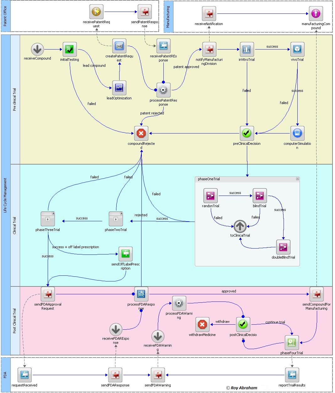
Figure 8: Physical Business Process Model

b) Creating and mapping Logical Data Dictionary (LDD). The LDD is a master reference table containing each and every attribute used in the business process. The meta data pertaining to each attribute is described in the table such as data type, data size, default value, list of values if enumerated, definition of attribute, container hierarchy (xPath) and type of attribute. The relative location of the attribute depends on the structure of the format where the attribute is located as shown in the figure below.

Figure 9: Data transformation and mapping in data formats.

The naming convention and associated meta data information are captured under each domain specific formats. For example, three attributes - order number, social security number and credit card type as it passes through different domain formats are shown below.

Figure 10: Logical Data Dictionary

The LDD is used as a reference document by analysts, architects, designers, developers, managers and testers for their respective needs. If LDD becomes too big to manage, it can be split into domain specific categories. The initial investment in the form of effort and time to build a Logical Data Dictionary is considerable. However, it is worth every penny as it prevents potential problems during the subsequent application development.
c) Creating the Canonical data structure. A canonical document, usually in XML format has to be derived based on the attributes collected in LDD. Thus, the LDD contains every attribute and its structure based on xPath. Different types of strategies can be used to arrive at the canonical XML. The canonical XML can be a subset of industry standard (such as SPL (Structured Product Labeling) , HL7, eCTD (electronic Common Techinical Document, HIPAA), a combination of SPL, HL7, eCTD, HIPAA and trading partner proprietary XML, derived from Business Objects or entirely a new XML structure as shown below.

Figure 11: Derivation of canonical data structure
d) Identifying and creating Unique Id. Every instance in the Business Process is identified by a unique id, similar to RFID (Radio Frequency IDentification). This id enables to maintain the life cycle of the instance even if it leaves the business process engine. For medicines, it can be National Drug code(NDC).

Figure 12: Canonical document


e) Develop necessary code within the created stub. Once physical BPM model is created, a stub code can be generated to hold the underlying business process. Generate and test the code within the stub.
f) Monitoring the Business Processes. Once deployed into production, each instance can be monitored using a monitor or BAM enabled portal interface as shown below.


Figure 13: Monitoring of a BPM instance at run time, rejected by pre-clinical vivo trial.


Figure 14: Monitoring of a BPM instance at run time, rejected by clinical Phase I trial (blind trial)

Figure 15: Monitoring of a B2M instance at run time, rejected by FDA.

Figure 16: Monitoring of a B2M instance at run time, medicine passed the trials and FDA and now in the marker and continuing with phase IV.

6) Big Data analysis in BPM:As BPM claim process gather large amount of data, those data can be used for big data analysis. These data can reside in various sources in various format such as Object data in S3, NoSQL data in DynamoDB, Relational data in RDS,  Warehouse data in RedShift, Archived data in Glacier and Streamed data in Kinesis. These data can be used, for example for predictive analysis. To test the billing claim variables against the time series (ARIMA - AutoRegressive Integrated Moving Average) model or against random walk (MCMC - Markov Chain Monte Carlo) using Python as shown below


Figure 17. Big Data analysis using EMR (Elastic Map Reduce) Cluster.


  •EC2 instances are created in a VPC(Virtual Private Cloud) in the respective Availability Zone.
  •A master node and slaves nodes are created in each EC2 instance.
  •Hadoop, Spark and Python code to run ARIMA mode is installed in the Master node. Hadoop and Spark are managed by YARN in the master node. Fail over is managed by AutoScaling group in the cluster.
  •Input data is read from any of the data sources and processed by the Python code. The results are written to one of the data storage for further analysis.

5) Conclusion: Most of the ills associated with the current application development are the inability of the business stake holder to have proper oversight. Most of the software development environment does not provide any such tools. The important benefits of BPM are,
a) SAVING MONEY: By completely automating all the business processes, virtually eliminates the unnecessary overheads in the loan processing and saves millions over the years.
b) LESS HUMAN ERROR: By automation, business processes have less human intervention and thus human error is minimized.
c) INCREASED PRODUCTIVITY: Faster loan processing enables better throughput (loans processed per unit time).
d) SUPERIOR OVERSIGHT: Upper management or business stakeholder gets a birds eye view of the entire loan process. In other words, management knows what is exactly going on rather than being told.
e) MONITORING AND OPTIMIZATION: In-depth monitoring of data at every step of the business process.
f) SUPERIOR ERROR HANDLING: Easy resubmission of process at a failed step.
g) ROI: Investing in BPM implementation gives the best return in the long run.
h) USER FRIENDLY: These models are extremely user friendly and provide a visual representation of the business processes which can easily be understood even by non-technical or uninitiated.
i) Fast Development and Implementation: Very fast and easy development life cycle and process refinement.
______________________________________________________________________
This document is for reference only. For actual implementation, please contact the author. No part of this document is to be used or reproduced without the written consent from the author (roychettan@gmail.com).


Principles Governing B2B and BPM Architecture

Roy Abraham


The following are some of the governing principles that must be enforced during a B2B integration project. These points indirectly affect the development methodology and non-functional requirements. Some of the principles described are applicable to the software architecture in general. However, these are described here in the B2Bi (Business-to-Business integration) architecture context. In general, B2Bi means, information exchange with trading partners without a web interface.

Keep components as loosely coupled as possible: This rule is applicable to all modern software application development. In B2Bi, this rule has special importance as some of the components of the enterprise may be indirectly exposed to the external trading partners. A new component may seamlessly be added or an unused component may be removed without affecting the entire application. The loose coupling can be achieved at component level or at message level. An application built upon loosely coupled (preferably, completely decoupled) components are more robust than application built upon tightly coupled components. If the components are decoupled, only the interface needs to be changed if either of the component changes. For example, a trading partner which has been using FTP as transport protocol has moved to HTTPS. The component responsible for FTP integration may be made dormant or even removed without affecting the rest of the application. Similarly, the component responsible for HTTPS integration may be introduced with out affecting the rest of the application system. Hence, component level decoupling is implemented with in the application system. On the other hand a message level decoupling is used across the application systems. A Message Oriented Middleware (MOM) is used to implement this among disparate application systems. In webservice space, it is called Enterprise Service Bus(ESB).


Divide and conquer: Apart from the negative connotation of this colonial rule, it is well suited for the software development. Most of the software systems are complex and difficult to manage and develop. This necessitates the division of the application system into smaller units for design and coding. These individual units loosely coupled with rest of such units make the entire application system. For example, the application may be horizontally layered into tiers and vertically split into sub-systems or domain as shown below. This division also enables component level decoupling. Two integration tiers sandwich the enterprise system, B2B integration tier facing the trading partners and EAI integration tier facing the rest of the enterprise systems.


A picture speaks a thousand words: The B2Bi is not visual. Hence, the design artifacts such as UML diagrams should be provided to expose hidden B2B processes. On the other hand BPM is visual depicting each process steps. Meaningful diagrams also leave a paper trail, which can be re-visited for re-design or re-engineering. Conceptual and Logical model diagrams which depict different processes and their interactions for non-technical members of the project such as Business Analysts and project management must be created. Physical Model diagrams which show different components and their relationship meant for technical members of the project such as developers are to be generated. A conceptual information flow between trading partners for a credit card transaction is shown below.

1. The customer creates a shopping cart and checks out the order,
2. The enterprise system of NAI sends the credit card information to a third party credit card processing company,
3. The credit card processing company routes the credit card information to the credit card company. Some credit card companies (like Discover and American Express) authorizes or declines the transaction.
4. Other credit card companies (like Visa or Mastercard) routes the credit card information to the credit card issuing bank.
5. The credit card issuing bank authorizes or declines the transaction.
6. The credit card processing company returns the response to NAI
7. The credit card issuing bank approves the transfer of money and credits NAI account
8. If the card issuing bank suspects fraud, it initiates the fraud alert and sends the information to an investigative government agency while declining the card.


Resist the temptation of using latest technology: (conversely, resist using extinct technology too. Implementing an application build on untested or sufficiently vetted technology put the project into tremendous risk. Many a times, the management or even the development community may be carried away only by looking at the positive aspects of a particular technology, put pressure on the architects to use that technology for the implementation of the project. If such a technology fails in the long run, the application becomes very susceptible to lack of technical and developer support. The architect has to identify the Technology Readiness Level of the technology she is implementing for the project which is almost always below the technology available at that time (Mankins,1995).

Follow the standards: It is a good software development practice to follow the established standards used in Business, technology, legal/regulatory space. This alleviates the Tower of Babel Problem associated with B2B integration. Hence, none of the trading partners have to adopt each others messaging standard, rather follow the industry standard. Also, building a messaging schema from scratch is extremely cumbersome and time consuming.


Business: Every vertical industry has developed a XML schema standard for B2B integration. For example, if the project involves an insurance based application, then the trading partners must follow ACORD standard unless proven otherwise.
Technology: If the application necessitates transformation of XML instances (say, ACORD XML instance to trading partner canonical XML instance), use XSLT standard. If the application is built on WebServices, trading partners must follow a particular WS-I basic profile. Following a technological standard also helps to avoid vendor lock-in.
Regulatory: If the application involves legal or national security related components, it must the SOX and/or Patriot Act compliant.


Defensive architecture: This concept is analogous to defensive driving. Not only the application must be robust and secure against the internal failures but also against the failures of the trading partners. For example, a XML message from a trading partner is intercepted by a malicious application and initiates a man-in-the-middle attack with a malicious data. Or, a trading partner advertently or inadvertently sends a message with an embedded Trojan horse.


Build a Canonical Schema: A canonical schema enables the application loosely coupled with the external trading partner schema (or industry standard schema) and the internal business components. The canonical schema acts as shock absorber for external schema changes and the redesign or re-factoring shocks of internal business components. A canonical schema and an associated Logical Data Dictionary(LDD) ensures disparate systems in the enterprise speaks same language. There different canonical strategies for building such canonical schema. They are canonical schema derived from underlying business objects or canonical schema derived from the industry standard.

Avoid making temporary fixes: Many a times, architects are forced to implement temporary solutions to application due to time or financial pressure from upper management. Unfortunately, many of the temporary fixes ended up become permanent especially the temporary fixes working fine. Later, the principle of if it ain’t broke, don’t fix it gives the justification not to fix it. Over the time, the application becomes less robust. Even if a temporary fix has to be applied for the current release, the temporary fix has to be corrected as first priority in the next release. Unfortunately, there are situations where temporary fixes are unavoidable. For example, the trading partner gives very short notice on the changes of purchase order schema.

Frequent scope creep: Even the traditional application development faces occasional scope creep. The presence of trading partners in the application integration increases the chances of scope creep in B2B integration projects. The complete definition and control of the project scope involving two or more business entities pose considerable challenge. Fruitful JAD sessions with trading partners is the best way to reduce scope creep.

Thinking about non-functional requirements all the time: The importance of non-functional requirements takes precedence mostly after the application go live. However, if not given proper consideration throughout the analysis, design and development, the application may not meet the stake holder expectations. Trying to fix non-functional requirements after going alive will be too little too late. The architect must be thinking about non-functional requirements such as performance, reliability, scalability, fail over, security, availability, maintainability, portability, re-usability and integrability throughout the analysis, design and development. Sometimes improving one may adversely affect others. For example, if the application is made more secure, it may adversely affect the performance of the application. Hence, the architect needs to prioritize the importance of each non-functional requirement as per the expectations of the stake holder. The architect must be asking himself (or thinking aloud with his team members) questions like,
How the application is supposed to handle if the trading partner sends a large document?
During down time, how to handle an incoming message?

Is the message needs to be secure at session level (using SSL) or end-to- end (using digital signature)?
What level of non-repudiation required? By receipt or by origin


Provide only those information which have business value: Trading partners must be provided with information what they need to know, not what they want or don’t want to know. Before sending out the information to the trading partner, those information which have no business value has to be filtered out of the message. This strategy not only makes the payload light weight but also avoid providing inadvertently internal information to the trading partners. In case of errors and exceptions, convey them in a business friendly manner to the trading partners. For example, in case of a database exception (like java SQLException), instead of sending the entire stack trace to the trading partner, catch the exception and create a business friendly message to the trading partner similar to- We are unable to process your request now. Please try to resend the request after some time.

Not all trading partners are equal: Conversely, some trading partners are more equal than others especially those ones who bring the revenue. Such trading partners can even impose their will on the architecture of the application to see whether it meets their own standards. Although, it is against the very tenants of B2Bi, the business reality bites sometimes. For example, an enterprise builds its B2Bi with XML / HTTP. However, a new integration with a trading partner with deep pockets and potential high revenue inflow requires flat file / FTP. Now, the enterprise has to re-architect to accommodate flat file / FTP. Trading partners comes with different colors and hues, some are Early Adopters (like small enterprises) and some are Early Majority (like large enterprises) and the rest in between them. Each trading partner comes with different Technology Readiness Level and different technology adoption time. So, an architect has to visualize and expect each and every such possible scenario. The key difference of such trading partners is shown below.


Type of trading partners (Geoghegan, 1994)


Innovation adoption of trading partners.

Avoid Over Engineering (and Under Engineering): Software and hardware technologies are improving over the time with constant innovation. Architecting a project with the current technology may become obsolete beyond a point in future. Architecting for the project beyond this point is a waste of time and resources. On the other hand, under engineering will not justify ROI (Return On Investment). Since the best technology is yet to come, any over engineering will also not justify ROI either. Unfortunately, it is extremely difficult to predict the technology readiness level of trading partners. The business reality may force to accommodate trading partners who bring revenue but use obsolete technology. In other words, architects must be ready to accept every type of trading partners. The arrival of cloud computing like AWS, helps to avoid software and hardware vendor lock.  


Never ever Assume: Because of information overload associated with the architecture, Architects are tempted to assume lot of technical information. For example, during a webservice based B2B integration, the Architect decides to use what she thought as the stable version of SOAP available at that time –SOAP1.0. On the other hand, architect of the trading partner decides to use the latest version of SOAP available at that time – SOAP 1.1. Such mistakes give rise to mutual mistrust and expensive recoding. Every details of information exchange with the trading partner (such as transport protocol, messaging protocol etc.) must be written down and be signed off by both parties. The colloquial etymology of Assume speaks for itself (Assume = Making Ass out of u and me).


Avoid multiple entries to the application system: Many of the B2Bi, also provide a web interface to the trading partner. In other words, the application is opening multiple doors for the information to enter, one via web and the other via B2B. The data validation and cleaning of data upon entering the system on both these channels and making the data in synch poses considerable challenge.


Use Code generating tools: Using code generating tools helps to speed up the development and create clean and optimized code. Such code generating tools are analogous to building a car. Instead of building a car by himself, a driver spends his time to master the driving skills. Even if he makes one, it may not be as good as one made by car making company. However, he has the confidence of changing a flat tire or a wiper blade. But he may never dare to touch the engine. Likewise, a developer uses code generating tools to create code and tweak the code here and there. Some of the code generating tools used for B2Bi is given below.
Creating XSLT code: Using a code generating tool, create XSLT code for mapping one XML to another during design time. At run time, XML instances are mapped using a transformer (say XALAN) using this XSLT. This saves considerable amount of time coding, debugging and optimizing the XSLT code.
Creating WSDL code: Many vendors provide tools to create WSDL from the webservice end points which are to be exposed.
Creating binding XML java classes: Using JAXB generator, binding java classes can be created from XML Schema at design time. At run time, XML instance are marshalled/unmarshalled with java class instances.


Avoid over crowding the team: Although team size may not be decided by the architect, an over crowded team adversely affects the productivity of the architect as she is the mentor to the team members and resolves the conflicts among team members. As a rule of thumb, five is a team; ten is a crowd. Beyond ten, any addition will have negative impact on the team effectiveness as shown below.
Geoghegan, W.H. (1994). Whatever happened to instructional technology? Paper presented at the 22nd Annual Conference of the International Business Schools Computing Association, Baltimore, Maryland July 17-20, 1994.

Mankins, John C., (6 April 1995), Technology Readiness Levels: A White Paper, NASA, Office of Space Access and Technology, Advanced Concepts Office.

____________________________________________________________________________
This document is for reference only. For actual implementation, please contact the author. No part of this blog is used or reproduced without the written consent from the roychettan@gmail.com